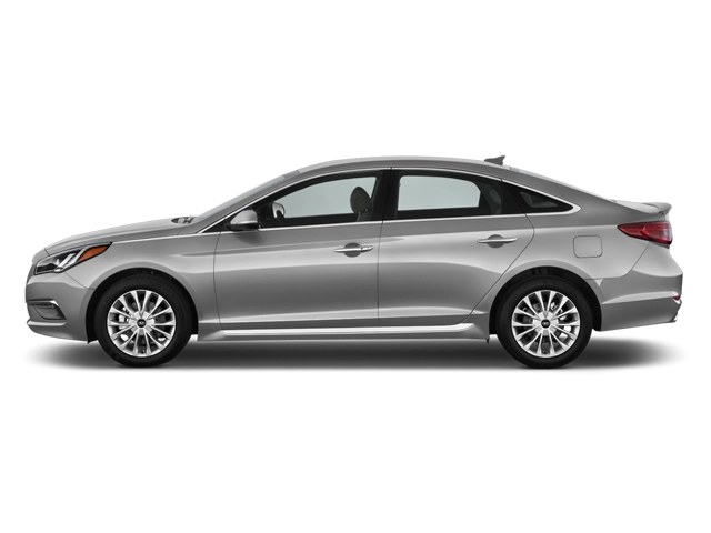
2024 Hyundai Sonata Owner's Manual
2024 Hyundai Sonata owners manual
Year:
2024
Make:
Hyundai
Model:
Sonata
Rating:
(3)

Online manual

Size:
8.35 MB

Table of Contents

OWNER’S MANUAL
1
Operation
1
Maintenance
1
Specifications
1
CAUTION: MODIFICATIONS TO YOUR HYUNDAI
2
TWO-WAY RADIO INSTALLATION
2
SAFETY AND VEHICLE DAMAGE WARNING
3
HYUNDAI VEHICLE OWNER PRIVACY POLICY
4
1. Introduction
7
Introduction
8
HYUNDAI Motor America
9
Guide to HYUNDAI Genuine Parts
10
1. What are HYUNDAI Genuine Parts?
10
2. Why HYUNDAI Genuine Parts?
11
3. How can you tell if you are purchasing HYUNDAI Genuine Parts?
11
How to use this manual
12
Safety messages
13
Fuel Requirements
14
Gasoline containing alcohol or methanol
14
Using Fuel Additives (except Detergent Fuel Additives)
15
Gasoline containing MMT
15
Detergent Fuel Additives
15
Operation in foreign countries
15
Vehicle Modifications
16
Vehicle Break-in Process
17
Vehicle Data Collection And Event Data Recorders
18
2. Vehicle Information, Consumer Information and Reporting Safety Defects
19
Exterior Overview (Front View)
20
The actual shape may differ from the illustration.
20
(1) Hood 5-55
20
(2) Front light 5-64, 9-59
20
(3) Tires and wheels 9-35
20
(4) Side view mirror 5-44
20
(5) Sunroof 5-51
20
(6) Front windshield wiper blades 5-74, 9-29
20
(7) Windows 5-47
20
(8) Front radar 7-4
20
Exterior Overview (Rear View)
21
The actual shape may differ from the illustration.
21
(1) Door 5-24
21
(2) Fuel filler door 5-59
21
(3) Rear combination light 5-64, 9-60
21
(4) Trunk 5-56
21
(5) High mounted stop light 9-60
21
(6) Antenna 5-100
21
(7) Wide-rear view camera 7-82
21
Interior Overview
22
The actual shape may differ from the illustration.
22
(1) Inside door handle 5-25
22
(2) Integrated memory system 5-30
22
(3) Side view mirror control switch 5-44
22
(4) Central door lock switch 5-26
22
(5) Power window switches 5-48
22
(6) Power window lock button 5-50
22
(7) Instrument panel illumination control switch 4-3
22
(8) ESC (Electronic Stability Control) OFF button 6-37
22
(9) Trunk open button 5-56
22
(10) EPB (Electronic Parking Brake) switch 6-30
22
(11) Hood release lever 5-55
22
(12) Steering wheel tilt/telescopic lever 5-33
22
(13) Steering wheel 5-32
22
(14) Seat 3-4
22
(15) Fuse box 9-48
23
Center Console Overview
24
The actual shape may differ from the illustration.
24
(1) Instrument cluster 4-2
24
(2) Horn 5-34
24
(3) Driver's front airbag 3-38
24
(4) Engine Start/Stop Button 6-5
24
(5) Rotary gear shift dial 6-10, 6-21
24
(6) Infotainment system 5-101
24
(7) Hazard warning flasher switch 8-2
24
(8) Automatic climate control system 5-77
24
(9) USB Port, USB Charger 5-99 / 5-95
24
(10) USB Charger/USB Port convert button 5-95
24
(11) USB Charger/Wireless charging system indicator 5-95 / 5-96
24
(12) Power outlet 5-94
24
(13) Wireless smartphone charging system 5-96
24
(14) Auto Hold button 6-33
24
(15) Drive mode button 6-47
25
(16) Parking/View button 7-83
25
(17) Cup holder 5-93
25
(18) Center console storage 5-92
25
(19) Glove box 5-92
25
(20) Passenger's front airbag 3-38
25
(21) USB Charger 5-95
25
Steering Wheel Control Overview
26
The actual shape may differ from the illustration.
26
(1) Lighting control lever 5-64
26
(2) Wiper and washer control lever 5-74
26
(3) Paddle shifter 6-17
26
(4) Driving Assist button 7-54
26
(5) Cluster display controls 4-25
26
(6) Vehicle Distance button 7-54
26
(7) Lane Driving Assist button 7-20
26
(8) Voice recognition button 5-101
26
(9) Audio remote control buttons 5-100
26
(10) Bluetooth® hands-free phone button 5-102
26
Engine Compartment Overview
27
Smartstream G2.5 T-GDI
27
The actual engine compartment in the vehicle may differ from the illustration.
27
(1) Engine coolant reservoir 9-22
27
(2) Battery 9-32
27
(3) Brake fluid reservoir 9-25
27
(4) Air cleaner 9-27
27
(5) Engine oil filler cap 9-19
27
(6) Engine oil dipstick 9-19
27
(7) Windshield washer fluid reservoir 9-26
27
(8) Fuse box 9-48
27
Smartstream G2.5 GDI
28
The actual engine compartment in the vehicle may differ from the illustration.
28
(1) Engine coolant reservoir 9-22
28
(2) Brake fluid reservoir 9-25
28
(3) Air cleaner 9-27
28
(4) Engine oil dipstick 9-19
28
(5) Engine oil filler cap 9-19
28
(6) Windshield washer fluid reservoir 9-26
28
(7) Fuse box 9-48
28
(8) Battery 9-32
28
Dimensions
29
Engine
29
Bulb Wattage
30
Tires And Wheels
31
Air Conditioning System
32
Vehicle Weight And Luggage Volume
32
*1 AT: Automatic Transmission
32
*2 DCT: Dual Clutch Transmission
32
Recommended Lubricants And Capacities
33
*1 Refer to the \Recommended SAE viscosity number\ section.
33
*2 Engine oils labeled Energy Conserving Oil are now available. Along with other additional benefits, they contribute to fuel economy by reducing the amount of fuel necessary to overcome engine friction. Often, these improvements are difficult to mea...
33
*3 If the transfer case/rear differential is submerged, visit an authorized HYUNDAI genuine products to replace the transfer/differential oil.
34
*4 Requires <API SN PLUS (or above) Full synthetic> grade engine oil. If a lower grade engine oil (mineral oil including semi-synthetic) is used, then the engine oil and engine oil filter must be replaced as indicated severe maintenance condition.
34
*5 To maintain the best braking performance and ABS/ESC performance, use genuine brake fluid that conform to specifications.
34
Recommended SAE viscosity number
34
*1 Requires <API SN PLUS (or above) Full synthetic> grade engine oil. If a lower grade engine oil (mineral oil including semi-synthetic) is used, then the engine oil and engine oil filter must be replaced as indicated severe maintenance condition.
34
Vehicle Identification Number (VIN)
36
Frame number (if equipped)
36
VIN label (if equipped)
36
Vehicle Certification Label
36
Tire Specification And Pressure Label
36
Engine Number
37
Smartstream G2.5 T- GDI
37
Smartstream G2.5 GDI
37
Air Conditioner Compressor Label
37
Open Source Software Notice
37
Consumer Information
38
Reporting Safety Defects
39
3. Seats & Safety System
41
Important Safety Precautions
42
Always wear your seat belt
42
Restrain all children
42
Airbag hazards
42
Driver distraction
42
Never drink or take drugs and drive
43
Control your speed
43
Keep your vehicle in safe condition
43
Seats
44
Driver's seat [A]
44
(1) Forward or rearward
44
(2) Seatback angle
44
(3) Seat cushion height
44
(4) Seat cushion angle (if equipped)
44
(5) Lumbar support (if equipped)
44
(6) Seatback bolster (if equipped)
44
(7) Head restraint
44
Front passenger's seat [B]
44
(1) Forward or rearward
44
(2) Seatback angle
44
(3) Seat height
44
(4) Head restraint
44
Rear seat [C]
44
(1) Head restraint
44
Infotainment system
45
Safety precautions
45
Airbags
45
Seat belts
46
Front seats
46
Reclining seatback
47
Manual seat controls
47
Forward and rearward adjustment
47
1. Pull up the seat slide adjustment lever and hold it.
47
2. Slide the seat to the position desired position.
47
3. Release the lever and make sure the seat is locked in place. Move forward and rearward without using the lever. If the seat moves, it is not locked properly.
47
Seatback angle
48
1. Lean forward slightly and lift up the seatback lever.
48
2. Carefully lean back on the seat and adjust the seatback to the desired position.
48
3. Release the lever and make sure the seatback is locked in place.
48
Seat height
48
Power seat controls
48
Forward and rearward adjustment
49
1. Push the control switch forward or rearward.
49
2. Release the switch once the seat reaches the desired position.
49
Seatback angle adjustment
49
1. Push the control switch forward or rearward.
49
2. Release the switch once the seatback reaches the desired position.
49
Seat cushion tilt/Seat height adjustment
49
1. Push the front portion of the control switch up to raise or down to lower the front part of the seat cushion.
49
2. Release the switch once the seat reaches the desired position.
49
1. Push the rear portion of the control switch up to raise or down to lower the height of the seat.
49
2. Release the switch once the seat reaches the desired position.
49
Lumbar support (for driver's seat)
50
1. Press the front portion of the switch (1) to increase support or the rear portion of the switch (2) to decrease support.
50
2. Release the switch once the lumbar support reaches the desired position.
50
Seat bolster adjustment (for driver's seat)
50
1. Push the adjustment lever clockwise, the seatback bolster will be adjusted inward. Push the switch counterclockwise, the seatback bolster will be adjusted outward.
50
2. Release the lever once the bolster reaches the desired position.
50
Seatback pocket
50
Rear seats
51
Folding the rear seats
51
1. Adjust the front seatback to the upright position and if necessary, slide the front seat forward.
51
2. Lower the rear head restraints to the lowest position by pushing and holding the release button (1) and pushing down on the head restraint (2).
51
3. Route the seat belt webbing to the outward of the rear seat to prevent the belts from being damaged.
51
4. Open the trunk and fold the seat back forward while pulling the seat folding lever (1).
51
5. To use the rear seat, lift and pull the seatback rearward. Pull the seatback firmly until it clicks into place. Make sure the seatback is locked in place and return the rear seat belt to the proper position.
52
1. Lift and push the seatback rearward while lifting up the front portion of the folding lever.
52
2. Push the seatback firmly until it clicks into place. Make sure the seatback is locked in place.
52
3. Route the seat belt webbing to the outward of the rear seat to prevent the belts from being damaged.
52
Armrest
52
Head restraint
53
Front seat head restraints
53
Adjusting the height up and down
54
1. Pull it up to the desired position (1).
54
1. Press and hold the release button (2) on the head restraint support.
54
2. Lower the head restraint to the desired position (3).
54
Removal/Reinstall
54
Manual adjustment seat
54
Power adjustment seat
54
1. Recline the seatback (2) with the seatback angle lever or switch (1).
54
2. Pull up the head restraint to the upmost position and press the release button (3) to remove the head restraint (4).
54
Manual adjustment seat
55
Power adjustment seat
55
1. Recline the seat back by pressing seatback angle lever or switch (3).
55
2. Put the head restraint poles (2) into the holes while pressing the release button (1).
55
3. Adjust the head restraint to the appropriate height.
55
4. Adjust the seatback angle (4) with the seatback angle lever or switch (3).
55
Rear seat head restraints
55
Adjusting the height up and down
55
1. Pull it up to the desired position (1).
55
1. Press and hold the release button (2) on the head restraint support.
55
2. Lower the head restraint to the desired position (3).
55
Removal
56
1. Raise the head restraint as far as it can go.
56
2. Press the head restraint release button (1) while pulling up the head restraint (2).
56
Reinstallation
56
1. Put the head restraint poles into the holes (2) while pressing the release button (1).
56
2. Adjust the head restraint to the appropriate height.
56
Seats Warmers
56
Front seat warmers
57
1. While the engine is running, press next to the driver's seat or front passenger's seat, which requires heating, from the climate control information screen.
57
2. When you press the button in the high state, it is high, and you can move it in the order of medium, low, and off by pressing the button.
57
Seat Belts
57
Seat belt safety precautions
57
Seat belt warning light
58
Driver's seat belt warning
58
Instrument cluster
58
Front passenger's seat belt warning
58
Rear passenger's seat belt warning
59
Seat belt restraint system
60
Driver's seat belt – 3-point system with emergency locking retractor
60
To fasten your seat belt:
60
Height adjustment (Front seat)
61
Front seat
61
To release your seat belt:
61
Passenger and rear seat belts – 3-point system with convertible locking retractor
61
To fasten your seat belt:
61
To release your seat belt:
62
Rear center seat belt (3-point rear center seat belt)
62
Pretensioner seat belt
62
(1) SRS airbag warning light
63
(2) Front retractor pretensioner
63
(3) SRS control module
63
(4) Rear retractor pretensioner
63
Load limiter
64
Additional seat belt safety precautions
64
Seat belt use during pregnancy
64
Seat belt use and children
65
Infant and small children
65
Larger children
65
Seat belt use and injured people
66
One person per belt
66
Do not lie down
66
Care of seat belts
66
Periodic inspection
66
Keep belts clean and dry
66
When to replace seat belts
66
Child Restraint System (CRS)
67
Children always in the rear
67
Child Restraint System (CRS)
67
Selecting a Child Restraint System (CRS)
68
Child Restraint System types
68
Rearward-facing Child Restraint System
68
Forward-facing Child Restraint System
69
Booster seats
69
Installing a Child Restraint System (CRS)
69
Lower Anchors and Tether for Children (LATCH System)
70
(1) Lower Anchor Position Indicator
70
(2) Lower Anchor
70
Securing a Child Restraint System with the \LATCH Anchors System\
71
1. Move the seat belt buckle away from the lower anchors.
71
2. Move any other objects away from the anchorages that could prevent a secure connection between the Child Restraint System and the lower anchors.
71
3. Place the Child Restraint System on the vehicle seat, then attach the seat to the lower anchors according to the instructions provided by the Child Restraint System manufacturer.
71
4. Follow the instructions of the Child Restraint System's manufacturer for proper installation and connection of the lower attachments on the Child Restraint System to the lower anchors.
71
Securing a Child Restraint System seat with \Top-tether Anchorage\ system
72
1. Route the Child Restraint System top-tether strap over the seatback. Placing the top tether strap, follow the instructions of the Child Restraint System manufacturer.
72
2. Connect the tether strap hook to the tether anchor, then tighten the top-tether strap according to the instructions of your Child Restraint System's manufacturer to firmly attach the Child Restraint System to the seat.
72
3. Check that the Child Restraint System is securely attached to the seat by pushing and pulling the seat forward-and-back and side-to-side.
72
Securing a Child Restraint System with a lap/shoulder belt
73
Automatic locking mode
73
1. Place the Child Restraint System on a rear seat and route the lap/shoulder belt around or through the Child Restraint System, following the Child Restraint System manufacturer's instructions. Make sure the seat belt webbing is not twisted.
73
2. Fasten the lap/shoulder belt latch into the buckle. Listen for the distinct \click\ sound.
73
3. Pull the shoulder portion of the seat belt all the way out. When the shoulder portion of the seat belt is fully extended, it will shift the retractor to the \Automatic Locking\ (child restraint) mode.
73
4. Slowly allow the shoulder portion of the seat belt to retract and listen for an audible \clicking\ or \ratcheting\ sound. This indicates that the retractor is in the \Automatic Locking\ mode. If no distinct sound is heard, repeat steps 3 and 4.
74
5. Remove as much slack from the belt as possible by pushing down on the Child Restraint System while feeding the shoulder belt back into the retractor.
74
6. Push and pull on the Child Restraint System to confirm that the seat belt is holding it firmly in place. If it is not, release the seat belt and repeat steps 2 through 6.
74
7. Double check that the retractor is in the \Automatic Locking\ mode by attempting to pull more of the seat belt out of the retractor. If you cannot, the retractor is in the \Automatic Locking\ mode.
74
Airbag - Advanced Supplemental Restraint System
75
The actual airbags in the vehicle may differ from the illustration.
75
(1) Driver's front airbag
75
(2) Passenger's front airbag
75
(3) Front Side airbag
75
(4) Rear Side airbag
75
(5) Curtain airbag
75
(6) Driver's knee airbag
75
SRS components
77
(1) Driver's front airbag module
77
(2) Passenger's front airbag module
77
(3) Side airbag modules
77
(4) Curtain airbag modules
77
(5) Retractor pretensioner
77
(6) Airbag warning light
77
(7) SRS control module (SRSCM)/Rollover sensor
77
(8) Front impact sensors
77
(9) Side impact sensors (acceleration)
77
(10) Side impact sensors (pressure)
77
(11) Driver's knee airbag module
77
(12) Occupant Classification System (OCS)
77
(13) Rear side airbag modules
77
Where are the airbags?
78
Driver's and passenger's front airbags
78
Driver's front airbag
78
Passenger's front airbag
78
Driver's knee airbag
78
Side airbags
79
Front seat
79
Rear seat
79
Curtain airbags
80
How does the airbags system operate?
81
Driver's front airbag (1)
83
Driver's front airbag (2)
83
Driver's front airbag (3)
83
Passenger's front airbag
83
What to expect after an airbag inflates
84
Noise and smoke from inflating airbag
84
SRS warning light
85
Occupant Classification System (OCS)
85
Main components of the Occupant Classification System
85
Condition and operation in the front passenger Occupant Classification System
87
*1 The system judges a person of adult size as an adult. When a smaller adult sits in the front passenger seat, the system may recognize him/her as a child depending on his/her physique and posture.
87
*2 Do not allow children to ride in the front passenger seat. When a larger child who has outgrown a Child Restraint System sits in the front passenger seat, the system may recognize him/her as an adult depending upon his/her physique or sitting posi...
87
*3 Never install a Child Restraint System on the front passenger seat.
87
*4 The PASSENGER AIRBAG \OFF\ indicator may turn on or off when a child above 12 months to 12 years old (with or without Child Restraint System) sits in the front passenger seat. This is a normal condition.
87
Proper seated position for OCS
90
Do not install a Child Restraint System on the Front Passenger's Seat
90
Why didn't my airbag go off in a collision?
91
Airbag collision sensors
91
[A] SRS control module/Rollover sensor
92
[B] Front impact sensor
92
[C] Side impact sensor (Pressure)
92
[D] Side impact sensor (Acceleration)
92
Airbag inflation conditions
93
Front airbags
93
Side and curtain airbags
93
Airbag non-inflation conditions
93
SRS care
95
Additional safety precautions
95
Adding equipment to or modifying your airbag equipped vehicle
95
Airbag warning labels
96
4. Instrument Cluster
97
Instrument Cluster
98
Type A
98
Type B
98
(1) Tachometer
98
(2) Speedometer
98
(3) Engine coolant temperature gauge
98
(4) Fuel gauge
98
(5) Warning and indicator lights
98
(6) Cluster display
98
Instrument cluster control
99
Instrument panel illumination
99
Control switch
99
Infotainment system
99
Gauges and meters
100
Speedometer
100
Type A
100
Type B
100
Tachometer
100
Type A
100
Type B
100
Engine coolant temperature gauge
101
Type A
101
Type B
101
Fuel gauge
101
Type A
101
Type B
101
Outside temperature gauge
102
Type A
102
Type B
102
Odometer
103
Type A
103
Type B
103
Distance to empty
103
Type A
103
Type B
103
Transmission shift indicator
104
Automatic transmission shift indicator
104
Type A
104
Type B
104
Dual clutch transmission shift indicator
104
Type A
104
Type B
104
Dual clutch transmission shift indicator in manual shift mode
105
Type A
105
Type B
105
Warning and indicator lights
105
Seat belt warning light
105
Airbag warning light
105
This warning light illuminates:
105
Parking brake warning light
106
This warning light illuminates:
106
If the brake fluid level in the reservoir is low:
106
1. Drive carefully to the nearest safe location and stop your vehicle.
106
2. With the engine stopped, check the brake fluid level immediately and add fluid as required (For more information, refer to the \Brake Fluid\ section in chapter 9). After adding brake fluid, check all brake components for fluid leaks. If a brake fl...
106
Dual-diagonal braking system
106
Anti-lock Brake System (ABS) warning light
107
This warning light illuminates:
107
Electronic Brake Force Distribution (EBD) System warning light
107
These two warning lights illuminate at the same time while driving:
107
Motor Driven Power Steering (MDPS) warning light
108
This warning light illuminates:
108
Charging system warning light
108
This warning light illuminates:
108
If there is a malfunction with either the alternator or electrical charging system:
108
1. Drive carefully to the nearest safe location and stop your vehicle.
108
2. Turn the engine off and check the alternator drive belt for looseness or breakage.
108
Engine oil pressure warning light
108
This warning light illuminates:
108
If the engine oil pressure is low:
108
1. Drive carefully to the nearest safe location and stop your vehicle.
108
2. Turn the engine off and check the engine oil level (For more information, refer to the \Engine Oil\ in chapter 9). If the level is low, add oil as required.
108
Low fuel level warning light
109
This warning light illuminates:
109
Malfunction Indicator Lamp (MIL)
109
This indicator light illuminates:
109
Master warning light
110
This warning light illuminates:
110
Electronic Parking Brake (EPB) warning light
110
This warning light illuminates:
110
Low tire pressure warning light
111
This warning light illuminates:
111
This warning light remains ON after blinking for about 60 seconds, or repeatedly blinks ON and OFF at 3 second intervals:
111
Driver Attention Warning light
111
This indicator light illuminates:
111
This indicator light blinks:
111
Lane Following Assist indicator light
112
This indicator light illuminates:
112
This indicator light blinks:
112
Lane Safety indicator light
112
This indicator light illuminates:
112
This indicator light blinks:
112
Forward Safety warning light
113
This warning light illuminates:
113
This warning light blinks:
113
LED headlight warning light
113
This warning light illuminates:
113
This warning light blinks:
113
Electronic Stability Control (ESC) indicator light
114
This indicator light illuminates:
114
This indicator light blinks:
114
Electronic Stability Control (ESC) OFF indicator light
114
This indicator light illuminates:
114
Immobilizer indicator light
114
This indicator light illuminates for up to 30 seconds:
114
This indicator light blinks for a few seconds:
114
This indicator light illuminates for a few seconds and goes off:
114
This indicator light blinks:
114
Turn signal indicator light
115
This indicator light blinks:
115
High beam indicator light
115
This indicator light illuminates:
115
Light ON indicator light
115
This indicator light illuminates:
115
High Beam Assist indicator light
115
This indicator light illuminates:
115
AUTO HOLD indicator light
116
This indicator light illuminates:
116
Speed Limiter indicator light
116
This indicator light illuminates:
116
Intelligent Speed Limit Assist indicator light
116
This indicator light illuminates:
116
Cluster display messages
117
Vehicle is On
117
Shift to P
117
Vehicle is in N. Press START button and shift to P
117
1. Press the Engine Start/Stop button. The Engine Start/Stop button goes to the ON position.
117
2. Shift the gear to P (Park).
117
3. Press the Engine Start/Stop button again, then the vehicle turns off.
117
Low key battery
117
Press brake pedal to start engine
117
Key not in vehicle
117
Press START button again
117
Press START button with key
117
Check BRAKE SWITCH fuse
118
Shift to P or N to start engine
118
Battery discharging due to external electrical devices
118
Door, Hood, trunk open indicator
118
Sunroof open indicator
118
Low tire pressure
119
Lights
119
Wiper
119
Front
119
Low washer fluid
120
Low fuel
120
Engine overheated
120
Check turn signal
120
Check headlight LED
120
Check AWD/4WD
120
Cluster Display
121
Cluster display control
121
View modes
121
Driving Assist mode
122
LKA/SCC/LFA/HDA
122
Turn by Turn (TBT) mode
122
Utility view
122
Current Trip
122
Since Refueling
122
Since Reset
123
Tire pressure
123
Driving force distribution (AWD)
123
Additional information display
123
Driver Assistance
123
Master warning mode
124
Vehicle Settings (infotainment System)
124
Vehicle Settings menu
124
Setting your vehicle
125
1. Press the SETUP button on the main keyboard.
125
2. Select Vehicle to change the settings for features.
125
5. Convenience Features
127
Accessing Your Vehicle
131
Smart key
131
(1) Door lock
131
(2) Door unlock
131
(3) Trunk open
131
(4) Panic
131
(5) Remote start
131
Locking your vehicle (1)
131
Button type
131
1. Close all doors, hood, and trunk.
131
2. Have the smart key with you.
131
3. Press the door handle button or press the Door Lock button (1) on the smart key. The hazard warning lights blink.
131
4. Make sure the doors are locked by pulling the outside door handle.
131
Touch sensor type
131
1. Close all doors, hood, and trunk.
131
2. Have the smart key with you.
131
3. Touch the door handle touch sensor to activate the door lock or press the Door Lock button (1) on the smart key. The hazard warning lights blink.
131
4. Make sure the doors are locked by pulling the outside door handle.
131
Unlocking your vehicle (2)
132
Button type
132
1. Have the smart key with you.
132
2. Press the door handle button or press the Door Unlock button (2) on the smart key. The hazard warning lights blink.
132
Touch sensor type
132
1. Have the smart key with you.
132
2. Grab the door handle to activate the door unlock touch sensor. The hazard warning lights blink two times.
132
Setting the Two Press Unlock feature
133
Setting the door lock/unlock prevention feature
133
To prevent unintentional door lock or unlock:
133
Smart key reminder
134
Opening the trunk (3)
134
1. Have the smart key with you.
134
2. Press the trunk open button on the vehicle or press and hold the trunk open button (3) on the smart key for more than 1 second. The hazard warning lights blinks two times and the trunk open.
134
Using panic alarm (4)
134
Remotely starting vehicle (5)
134
1. Press the door lock button on the smart key within about 32 ft. (10 m) from the vehicle.
134
2. Press the Remote Start button (4) on the smart key within 2 seconds from when you have pressed the door lock button. The engine starts.
134
3. To turn off the engine, press the Remote Start button (4) once.
134
Starting the vehicle
135
Mechanical key
135
Key cylinder (Driver door)
135
Loss of a smart key
135
Smart key precautions
136
1. This device may not cause harmful interference.
136
2. This device must accept any interference received, including interference that may cause undesired operation.
136
3. Changes or modifications not expressly approved by the party responsible for compliance could void the user's authority to operate the device.
136
Replacing the battery
137
1. Insert a slim tool into the slot (1) and gently open the rear cover.
137
2. Remove the old battery and insert a new battery. Make sure the battery position is correct.
137
3. Reinstall the rear cover of the smart key.
137
Immobilizer system
138
1. This device may not cause harmful interference, and
138
2. This device must accept any interference received, including interference that may cause undesired operation.
138
3. Changes or modifications not expressly approved by the party responsible for compliance could void the user's authority to operate the device.
138
Hyundai Digital Key
139
Digital key (smartphone)
139
Setting your smartphone
139
Registering your digital key (smartphone)
139
[A] Vehicle authentication pad (wireless charging pad)
139
1. Turn on the vehicle with a smart key and have your smart key with you in the vehicle.
139
2. Put the gear in P (Park), from the infotainment system Settings menu, select Setup > Vehicle > Digital keys > Smartphone key > My Smartphone Key.
139
3. After selecting Digital Key > Set Up Digital Key from the Bluelink App in the smartphone, register the digital key according to the guidance in the smartphone screen.
139
4. Press Save button in the infotainment system to start registration.
140
Using the digital key (smartphone)
141
Digital key touch control
141
Digital key close proximity control
141
Locking/Unlocking the doors
141
Samsung & Google Pixel smartphones
141
[A] Door handle authentication pad
141
[B] NFC Antenna
141
Apple iPhone
141
[A] Door handle authentication pad
141
[B] NFC Antenna
141
Starting the vehicle
142
Operating the trunk
143
Deleting your digital key (smartphone)
144
Deleting all registered digital key (smartphone)
144
Deleting my registered digital key (smartphone)
145
Digital key (Card key)
145
How to register Digital key (Card Key)
145
[A] Vehicle authentication pad (Wireless charging pad)
145
1. Have both of your smart keys with you in the vehicle.
145
2. Select Setup > Vehicle > Digital Keys > NFC Card Key from the Setup menu, and check whether \Use\ is selected in the infotainment system.
145
3. Place your card key on the vehicle authentication pad (wireless charging pad) while the engine is on.
145
4. Register your card key by selecting Setup > Vehicle > Digital Keys > NFC Card Key > Save from the Settings menu in the infotainment system.
145
Using the digital key (card key)
146
[A] Door handle authentication pad
146
[B] Card key NFC Antenna
146
Locking/Unlocking the doors
146
Starting the vehicle
146
Deleting your digital key (card key)
147
1. Turn on the engine with a smart key. Have your smart key with you in the vehicle.
147
2. From the infotainment system settings menu, select Setup > Vehicle > Digital Keys > Card Key > Delete.
147
Personalized profile and vehicle settings
147
Linking/Unlinking profile
148
How to link user profile
148
1. Select Setup > User Profile > Profile Settings > Link Digital Key (Smartphone) from the Settings menu in the infotainment system.
148
2. Select \Link\ to connect the registered smartphone's digital key and the user's profile.
148
3. Follow the instructions according to the message on the infotainment system.
148
How to unlink user profile
148
Vehicle personalization operation
148
Used vehicle/Digital key maintenance
149
Purchasing used vehicle
149
Digital Key maintenance
149
Limitations of the system
149
Door Locks
150
Operating door locks from outside the vehicle
150
Using the mechanical key
150
[A] Lock
150
[B] Unlock
150
1. Press the lever located under the cover with the mechanical key. (1)
150
2. While pushing the lever so that the mechanical key does not fall out of the cover hole, slowly push it towards the rear of the vehicle and remove the cover. (2)
150
3. After removing the cover, only the driver's door can be locked or unlocked by using the mechanical key. (3)
150
Using the smart key
150
In case of an emergency
151
1. Open the door.
151
2. Insert a small blade tool (e.g. screwdriver or similar) into the emergency door lock hole and turn it counterclockwise for left side door, or turn it clockwise for right side door.
151
3. Close the door securely.
151
Operating door unlocks from inside the vehicle
151
With the door inside handle
151
Front door
151
Rear door
151
With the central door lock/unlock switch
152
Driver's door
152
Front passenger's door
152
Auto Door Lock/Unlock features
153
Impact sensing door unlock system
153
Auto lock enable on shift
153
Auto unlock on shift to P
153
Child-protector rear door locks
153
Theft-alarm System
154
(1) WARNING
154
(2) SECURITY SYSTEM
154
Rear Occupant Alert (ROA)
155
System setting
155
System operation
155
Type A
155
Type B
155
Integrated Memory System
156
Storing memory positions
156
1. Shift to P (Park) while the Engine Start/Stop button is in the ON position.
156
2. Adjust the driver's seat position and side view mirror position to the driver's field of view.
156
3. Press the SET button. The system beeps once and notifies you \Press button to save settings\ will appear on the infotainment.
156
4. Press one of the memory buttons (1 or 2) within 4 seconds. The system beeps twice when successfully stored and notifies you \Driver 1 (or 2) settings saved\ will appear on the infotainment.
156
Recalling memory positions
156
1. Shift to P (Park) while the Engine Start/Stop button is in the ON position.
156
2. Press the desired memory button (1 or 2). The system beeps once and then the driver's seat position and side view mirror position are automatically adjusted to the stored positions.
156
3. \Driver 1 (or 2) settings applied\ appears on the infotainment.
156
Resetting integrated memory system
157
1. Stop the vehicle and open the driver's door with the Engine Start/Stop button in the ON position and the vehicle shifted to P (Park).
157
2. Adjust the driver's seat and seatback to the foremost position.
157
3. Press the SET button and push forward the driver's seat switch simultaneously (about two seconds).
157
4. Release the SET button and the driver's seat switch when a beep sounds.
157
While resetting integrated memory system
157
Seat easy access operation
157
Steering Wheel
158
Motor Driven Power Steering (MDPS)
158
Tilt/Telescopic steering
159
Manual adjustment
159
1. Pull down the lock-release lever (1).
159
2. Adjust the steering wheel to the desired angle (2) and distance forward/back (3).
159
3. Pull up the lock-release lever up to lock the steering wheel in place.
159
Horn
160
Haptic warning/Steering wheel vibration warning
160
Setting haptic warning
160
Mirrors
160
Inside rearview mirror
160
Day/night rearview mirror
161
[A] Day
161
[B] Night
161
Electrochromic mirror
161
[A] Sensor
161
Electrochromic mirror (ECM) with HomeLink® system
161
(1) HomeLink Channel 1
161
(2) HomeLink Channel 2
161
(3) HomeLink Channel 3
161
(4) Garage Door Opener Status Indicator: Closing or Closed
161
(5) HomeLink Operation Indicator
161
(6) Garage Door Opener Status Indicator: Opening or Opened
161
(7) HomeLink User Interface Indicator
161
Automatic-Dimming Night Vision Safety™ (NVS®) Mirror
162
Integrated HomeLink® Wireless Control System
162
1. Programming HomeLink®
163
1) Programming Preparation
163
1. When programming a garage door opener, it is advised to park the vehicle outside of the garage.
163
2. It is recommended that a new battery be placed in the handheld transmitter of the device being programmed to HomeLink for quicker training and accurate transmission of the radio-frequency signal.
163
3. Press the Start/Stop button to the ACC (Accessory) position for programming of HomeLink.
163
2) Programming a New HomeLink®
163
1. Press and release the HomeLink button (1), (2) or (3), you would like to program. The HomeLink indicator light (7) will flash orange slowly (if not, perform the steps of \Erasing HomeLink Buttons\ section, and start over).
163
2. Position the garage door opener remote 1-3 inches (2-8 cm) away from the HomeLink buttons.
163
3. While the HomeLink indicator light (7) is flashing orange, press and hold the handheld remote button. Continue pressing the handheld remote button until the HomeLink indicator light (7) light changes from orange to green. You may now release the h...
163
4. Wait until your garage door comes to a complete stop, regardless of position, before proceeding to the next steps.
163
5. Press and release the HomeLink button you are programming and observe the indicator light.
164
6. At the garage door opener motor, (security gate motor, etc.) locate the 'Learn', 'Smart', 'Set' or 'Program' button. This can usually be found where the hanging antenna wire is attached to the motor-head unit (see the device's manual to identify t...
164
[A] Learn button
164
7. Firmly press and release the 'Learn', 'Smart', 'Set' or 'Program' button. You now have up to 30 seconds in which to complete the next step.
164
8. Return to the vehicle and firmly press, hold for two seconds and release, the HomeLink button up to three times in a row slowly. Do not press the HomeLink button rapidly. As soon as you see the garage door start to move, stop pressing any buttons ...
164
3) Two-Way Communication Programming (For select garage door openers)
164
1. In your vehicle, press and hold the programmed HomeLink button for 2 seconds, then release. Confirm that the garage door is moving. AFTER it stops, you will have one minute to complete the following steps:
165
2. On your garage door opener in your garage, locate the 'Learn' button (usually near where the hanging antenna wire is attached to the garage door opener). If there is difficulty locating this button, reference the device's owner's manual.
165
3. Press and release the 'Learn' button.
165
4. A light on your garage door opener may flash, and your Two-Way Communication indicators (4), (6) in your vehicle may flash, confirming completion of the process.
165
5. Return to the vehicle and firmly press and release the programmed HomeLink button to activate your garage door. The Two-Way Communication indicators (4), (6) flash in orange when the door is moving. Do not make any additional button presses until ...
165
6. Your Two-Way Communication programming is now complete.
165
4) Canadian Programming
165
2. Operating HomeLink®
166
1) Operating HomeLink®
166
1. Press and release the desired programmed HomeLink button (1, 2 or 3).
166
2) Two-Way Communication Display Behavior
166
1. Press and release one of the programmed HomeLink buttons (1, 2 or 3).
166
2. The indicator (4) and (6) operates as below, if your garage door opener has Two-Way Communication functionality.
166
3) Recalling Garage Door Status
167
3. Erasing HomeLink® Buttons
167
1) Erasing and Reprogramming a Single HomeLink® Button:
167
1. Press and hold the desired HomeLink button you want to re-program. DO NOT release the button.
167
2. The HomeLink indicator light (7) will illuminate solid green. Release the button as soon as the HomeLink indicator light (7) begins to flash orange, usually about 20 seconds.
167
3. Proceed with the steps in the \Programming a New HomeLink Button\ section.
167
2) The following instructions will erase ALL HomeLink® programming from ALL buttons:
167
1. Press and hold the buttons (1) and (3) simultaneously
167
2. The HomeLink indicator light (7) will illuminate solid Orange for about 10 seconds
167
3. Release the buttons once the HomeLink indicator light (7) changes to Green and flashes rapidly
167
4. Now all three HomeLink buttons (1), (2) and (3) are cleared of any programming
167
FCC (USA) and ISED (Canada)
168
FCC (Htats-Unis) et ISED (Canada)
168
Mejico
168
HomeLink 5 Programing Flow Chart
169
Side view mirrors
170
Adjusting the side view mirrors
170
1. Press the switch (1) to the L (left side) or R (right side) to select the side view mirror you want to adjust.
170
2. Use the mirror adjustment control switch (2) to position the selected mirror up, down, left, or right.
170
3. After adjustment, press the switch (1) to the middle to prevent unintended adjustment.
170
Folding the side view mirrors
171
Reverse parking aid
171
How it works
171
Reverse parking aid user settings mode
172
1. Make sure the vehicle is stopped.
172
2. Depress the brake pedal and shift the gear to R (Reverse). When L or R switch is pressed, both side view mirrors move downward to the basic set position.
172
3. Press the L or R switch to select the side view mirror you want to adjust. Then press \, , , \ switch to adjust the side view mirror to the desired angle.
172
4. After adjusting the angle to save the adjusted side view mirror angle, shift the gear to another position other than R (Reverse), or change the L and R switch to the neutral position (L and R switch is not pressed).
172
5. Set the other side view mirror following the above procedure 1 to 4.
172
Resetting reverse parking aid user settings mode
172
Windows
173
Front / Rear
173
(1) Driver's door power window switch
173
(2) Front passenger's door power window switch
173
(3) Rear door (left) power window switch
173
(4) Rear door (right) power window switch
173
(5) Window opening and closing
173
(6) Automatic power window
173
(7) Power window lock button
173
Power windows
174
Window opening and closing
174
Auto up/down window
174
Resetting the power windows
175
1. Press the Engine Start/Stop button to the ON position.
175
2. Close the window and continue pulling up on the power window switch for at least one second.
175
Automatic reversal
175
Power window lock button
176
Remote window opening feature
176
Panoramic Sunroof
177
Power sunshade
177
Tilt open/close
178
Slide open/close
178
Automatic reversal
179
Resetting the sunroof
180
1. Start the vehicle in P (Park).
180
2. Make sure the power sunshade and sunroof glass are in the fully closed position.
180
3. Release the switch when the power sunshade and sunroof glass is fully closed.
180
4. Push the switch forward until the power sunshade and sunroof glass moves slightly. Then release the switch.
180
5. Push and hold the sunroof switch forward again until the power sunshade and sunroof glass slide open and close.
180
Sunroof open warning
180
Hood
181
Opening the hood
181
1. Park the vehicle and apply the parking brake.
181
2. Pull the hood release lever to unlatch the hood. The hood pops open slightly.
181
3. Go to the front of the vehicle, raise the hood slightly, push up the secondary hood release lever (1) inside of the hood center and lift the hood (2).
181
Closing the hood
181
1. Before closing the hood, check in and around the engine compartment to ensure the following:
181
2. Lower the hood until it is about 12 inches (30 cm) above the closed position and then let it drop.
181
3. Check the hood has locked properly. If the hood is raised slightly, open it again and drop it from a little higher. Check again.
181
Trunk
182
Opening the trunk
182
Opening from outside
182
Opening from inside
182
Closing the trunk
182
Emergency trunk safety release
183
Smart Trunk
183
Using smart trunk
183
1. Settings
184
2. Detect and Alert
184
3. Automatic opening
184
Deactivating smart trunk
184
Detecting area
185
Fuel Filler Door
185
Opening the fuel filler door
185
1. Turn the engine off.
185
2. Push the fuel filler door (1) near the 3 o'clock position.
185
3. Pull the fuel filler door (1) outward to access the fuel tank cap.
185
4. To remove the fuel tank cap (2), turn it counterclockwise. You may hear a hissing noise as the pressure inside the tank equalizes.
185
5. Place the cap on the fuel filler door.
185
Closing the fuel filler door
186
1. To install the fuel tank cap, turn it clockwise until it \clicks\ one time.
186
2. Close the fuel filler door until it is latched securely.
186
Vehicle System OTA Update
187
Downloading software
187
Approving software update
187
Preparing software update
188
Updating software
188
Exterior Lights
190
Lighting control
190
(1) OFF
190
(2) AUTO light
190
(3) Parking light
190
(4) Headlight
190
AUTO headlight
190
Parking light ()
191
Headlight ()
191
High Beam Operation
191
Turn signals and lane change signals
192
One touch turn signal
192
Battery saver function
192
Headlight delay function
192
Interior button lights
193
Daytime Running Light (DRL)
193
Welcome system
193
Door handle light
194
Headlight and parking light
194
Interior light
194
High Beam Assist (HBA)
195
Detecting sensor
195
(1) Front view camera
195
High Beam Assist settings
195
High Beam Assist operation
196
High Beam Assist malfunction and limitations
196
High Beam Assist malfunction
196
Limitations of High Beam Assist
197
Interior Lights
198
Interior lamp Auto off
198
Front lamps
198
Rear lamps
199
Room lamp (if equipped)
199
Personal lamp (if equipped)
199
Vanity mirror lamp
199
Ambient light
199
[A] Driver seat door, passenger seat door
199
[B] Crash pad
199
Luggage compartment lamp
200
Wipers And Washers
200
Windshield wipers
200
AUTO (Automatic) control
201
Windshield washers
202
Recirculating air when washer fluid is used
202
Automatic Climate Control System
203
The climate control system buttons may differ depending on vehicle specification.
203
(1) Driver's temperature control
203
(2) Passenger's temperature control
203
(3) AUTO (automatic control)
203
(4) SYNC(Same control for all seats based on the driver's seat)
203
(5) Fan speed control
203
(6) Mode selection
203
(7) OFF
203
(8) A/C (air conditioning)
203
(9) Air intake control
203
(10) Front windshield defroster
203
(11) Rear window defroster
203
Automatic heating and air conditioning
204
1. Press the AUTO button. The modes, fan speeds, air intake, and air conditioning are controlled automatically by the temperature setting.
204
2. Turn left or right the temperature control knob to set the desired temperature. If the temperature is set to the lowest setting, the air conditioning system operates continuously. After the interior has cooled sufficiently, adjust the knob to a hi...
204
Manual heating and air conditioning
205
1. Start the engine.
205
2. Set the mode to the desired position. For improving the effectiveness of heating and cooling, select:
205
3. Set the temperature control to the desired position.
205
4. Set the air intake control to the outside (fresh) air position.
205
5. Set the fan speed control to the desired speed.
205
6. If air conditioning is desired, turn on the air conditioning system.
205
Mode selection
205
Air flow direction
206
Front windshield defroster [A], [D]
207
Instrument panel vents
207
Front
207
Rear
207
Temperature control
208
Temperature conversion (°C ↔ °F)
208
SYNC (Adjusting the driver and passenger side temperature equally)
208
Adjusting the temperature and air flow direction equally
208
Adjusting the temperature individually
208
Air intake control
209
Recirculation mode
209
Outside (fresh) mode
209
Fan speed control
209
Air conditioning
210
OFF mode
210
System maintenance
210
Cabin air filter
210
Checking the amount of air conditioner refrigerant
211
Air conditioning refrigerant label
211
(1) Classification of refrigerant
211
(2) Amount of refrigerant
211
(3) Classification of compressor lubricant
211
(4) Caution
211
(5) Flammable refrigerant
211
(6) To require registered technician to service air conditioning system
211
Windshield Defrosting And Defogging
212
Automatic climate control system
212
To defog inside windshield
212
(1) Select the desired fan speed.
212
(2) Select the desired temperature.
212
(3) Press the defroster button ()
212
(4) The air conditioning turns on according to the detected ambient temperature, the outside (fresh) air mode and higher fan speed are selected automatically.
212
To defrost outside windshield
212
(1) Set the fan speed to the highest position.
212
(2) Set the temperature to the hottest (HI) position.
213
(3) Press the defroster button ()
213
(4) The air conditioning turns on according to the detected ambient temperature and the outside (fresh) air mode is selected automatically.
213
Defogging logic
213
1. Press the Engine Start/Stop button to the ON position.
213
2. Press the defroster button ( ).
213
3. While pressing the air conditioning button, press the air intake control button at least 5 times within 3 seconds
213
Rear window defroster
213
Side view mirror defroster
213
Climate Control Additional Features
214
Air conditioning auto-drying
214
Turning Air conditioning auto-drying on or off
214
Operating conditions
214
Non-operating conditions
214
Auto defogging system
214
Turning the Auto defogging system on or off
215
Climate control system
215
Infotainment system
215
Auto dehumidify
216
Turning Auto dehumidify on or off
216
Climate control system
216
Infotainment system
216
Sunroof inside air recirculation
216
Recirculating air when washer fluid is used
216
Turning Activation on a washer fluid use on or off
216
Climate control system
216
Infotainment system
216
Recirculating air when entering a tunnel
217
Storage Compartment
218
Center console storage
218
Glove box
218
Interior Features
219
Cup holder
219
Front seat
219
Rear seat armrest
219
Sunvisor
220
Power outlet
220
Center console storage (inside)
220
USB charger
221
Front
221
Rear
221
Wireless smartphone charging system
222
(1) Indicator light
222
(2) Charging pad
222
Charging your smartphone
222
1. Remove other items, including the smart key, from the wireless charging unit. If not, the wireless charging process may be interrupted. Place the smartphone on the center of the charging pad.
222
2. The system is available when all doors are closed, and when the Start/Stop button is in the ON or START position.
222
3. You can turn ON or OFF the wireless charging function from the Setup menu in the infotainment system. Select:
222
4. The indicator light is orange when the smart phone is charging. The indicator light will turn green when phone charging is complete.
223
1. This device may not cause harmful interference.
224
2. This device must accept any interference received, including interference that may cause undesired operation.
224
3. Changes or modifications not expressly approved by the party responsible for compliance could void the user's authority to operate the device.
224
Clock
224
Coat hook
224
Rear
224
Floor mat anchor(s)
225
Infotainment System
225
USB Port
225
Antenna
226
Steering wheel remote controls
226
SEEK/PRESET ( / ) (1)
227
/ VOL -) (2)
227
MODE (3)
227
MUTE () (4)
227
Infotainment system
227
Voice recognition
227
Bluetooth® wireless technology
228
(1) Call/Answer/Call end button
228
(2) Microphone
228
6. Driving Your Vehicle
229
Before Driving
231
Before entering the vehicle
232
Before starting
232
Engine Start/Stop Button
233
Engine Start/Stop button positions
234
Starting the engine
235
1. Always carry the smart key with you.
235
2. Make sure the parking brake is applied.
235
3. Make sure the gear is in P (Park).
235
4. Depress the brake pedal.
235
5. Press the Engine Start/Stop button.
235
Turning off the engine
236
1. Stop the vehicle and depress the brake pedal fully.
236
2. Make sure the gear is in P (Park).
236
3. Apply the parking brake.
236
4. Press the Engine Start/Stop button to the OFF position.
236
5. Take the key with you when you leave the vehicle.
236
Remotely starting the engine
236
1. Press the door lock button within 32 ft. (10 m) from the vehicle.
236
2. Press and hold the remote start button () for over 2 seconds within 4 seconds.
236
Vehicle Auto-Shut Off
237
Operating conditions
237
Deactivating conditions
237
System operation
237
Resetting cluster timer
237
Automatic Transmission
238
Automatic Transmission (Rotary gear shift dial type)
238
[A] Rotary gear shift dial
238
[B] P button
238
Automatic Transmission (Rotary gear shift dial type) operation
239
P (Park)
239
Automatic gear shift to P (Park)
239
R (Reverse)
240
N (Neutral)
240
To stay in N (Neutral) when vehicle is OFF
241
1. Turn off Auto Hold and apply the parking brake when the engine is running.
241
2. Rotate the shift dial to N (Neutral) while depressing the brake pedal.
241
3. When you take your foot off the brake pedal, the message \Press and hold the OK button on the steering wheel to stay in Neutral\ appears on the cluster display.
241
4. Press and hold the OK button [A] on the steering wheel for more than 1 second.
241
5. When the message \Vehicle will stay in (N). Change gear to cancel.\ appears on the cluster display, turn the vehicle off while depressing the brake pedal.
241
D (Drive)
241
Shift-lock system
242
1. Depress and hold the brake pedal.
242
2. Start the engine or press the Engine Start/Stop button to the ON position.
242
3. Shift the gear while depressing the brake pedal.
242
When the battery is discharged
242
1. Connect the battery cables from another vehicle or from a another battery to the jump-starting terminals inside the engine compartment.
242
2. Apply the Electronic Parking Brake (EPB) with the Engine Start/Stop button in the ON position.
242
3. Shift the gear to the N (Neutral) position. Refer to the \To stay in N (Neutral) when vehicle is OFF\ in this chapter.
242
Cluster display message
242
Press brake pedal to change gear
242
Shift to P after stopping
242
Check P button
243
Shifter system malfunction
243
Check shifter dial
243
Vehicle will stay in (N). Change gear to cancel
243
PARK malfunction. Engage parking brake when parking vehicle.
244
Rotary shifter stuck
244
Transmission Hot! Park with engine on
244
Vehicle Power limited due to high transmission temperature
244
Avoid shifting for a few seconds
245
Trans cooled. Resume driving
245
Paddle shifter (manual shift mode)
245
Parking
246
Good driving practices
246
Dual Clutch Transmission
247
Dual clutch Transmission (Rotary gear shift dial type)
249
[A] Rotary gear shift dial
249
[B] P button
249
Dual clutch Transmission (Rotary gear shift dial type) operation
249
P (Park)
249
Automatic gear shift to P (Park)
249
R (Reverse)
250
N (Neutral)
250
To stay in N (Neutral) when vehicle is OFF
251
1. Turn off Auto Hold and apply the parking brake when the engine is running.
251
2. Rotate the shift dial to N (Neutral) while depressing the brake pedal.
251
3. When you take your foot off the brake pedal, the message \Press and hold the OK button on the steering wheel to stay in Neutral\ appears on the cluster display.
251
4. Press and hold the OK button [A] on the steering wheel for more than 1 second.
251
5. When the message \Vehicle will stay in (N). Change gear to cancel.\ appears on the cluster display, turn the vehicle off while depressing the brake pedal.
251
D (Drive)
251
Shift-lock system
252
1. Depress and hold the brake pedal.
252
2. Start the engine.
252
3. Shift the gear while depressing the brake pedal.
252
When the battery is discharged
252
1. Connect the battery cables from another vehicle or from a another battery to the jump-starting terminals inside the engine compartment.
252
2. Apply the parking brake with the Engine Start/Stop button in the ON position.
252
3. Shift the gear to the N (Neutral) position. Refer to the \Dual clutch Transmission (Rotary gear shift dial type)\ in this chapter.
252
Parking
252
Cluster display message
253
Press brake pedal to change gear
253
Shift to P after stopping
253
Shifter system malfunction
253
Check shifter dial
253
Check P button
254
Rotary shifter stuck
254
Transmission overheated warning
254
Transmission Hot! Park with engine on
254
Vehicle Power limited due to high transmission temperature
255
Trans cooled. Resume driving
255
Paddle shifter (manual shift mode)
255
Good driving practices
256
Braking System
257
Power-assist brakes
257
Disc brakes wear indicator
257
Electronic Parking Brake (EPB)
258
Applying the parking brake
258
To apply EPB (Electronic Parking Brake):
258
1. Depress and hold the brake pedal.
258
2. Pull up the EPB switch.
258
EPB (Electronic Parking Brake) may be automatically applied when:
258
Emergency braking
258
Releasing the parking brake
258
To release EPB (Electronic Parking Brake):
258
1. Press the Engine Start/Stop button to ON or START position.
258
2. Press the EPB switch while depressing the brake pedal.
258
To release EPB (Electronic Parking Brake) automatically:
258
When the EPB (Electronic Parking Brake) does not release
259
Warning messages
259
To release EPB, fasten seatbelt and close door, hood and trunk
259
AUTO HOLD turning Off! Press brake pedal
260
Parking brake automatically engaged
260
EPB malfunction
260
Parking brake warning light
261
Auto hold
261
To apply:
261
[A] White
261
1. With the driver's door, hood, and trunk closed, press the AUTO HOLD button. The white AUTO HOLD indicator comes on and the system is in standby.
261
2. When you stop the vehicle completely by depressing the brake pedal, Auto Hold maintains the brake pressure to hold the vehicle stationary. The indicator changes from white to green.
261
3. If EPB is applied, Auto Hold will be released.
261
To release:
262
To cancel:
262
[A] Light off
262
1. Depress and hold the brake pedal.
262
2. Press the AUTO HOLD button.
262
Warning messages
263
Parking brake automatically engaged
263
AUTO HOLD turning Off! Press brake pedal
263
Press brake pedal to deactivate AUTO HOLD
263
Anti-Lock Brake System (ABS)
264
Using ABS
264
Electronic Stability Control (ESC)
265
ESC operation
266
ESC ON condition
266
When operating
266
ESC OFF condition
266
Indicator lights
267
ESC indicator light (blinks)
267
ESC OFF indicator light (comes on)
267
ESC OFF usage
267
When Driving
267
Vehicle Stability Management (VSM)
268
VSM operation
268
When operating
268
VSM OFF condition
268
Hill-Start Assist Control (HAC)
269
Good braking practices
269
Launch Control
270
Launch Control operation and release
270
Prerequisite for activation
270
To ready Launch Control
270
mode in the infotainment system at Setup > Vehicle > Drive mode > MY DRIVE MODE. And set MY DRIVE mode using the drive mode selection switch. (The MY DRIVE mode selection appears on the instrument cluster.)
270
2. Turn off ESC by pressing the ESC OFF button for more than 3 seconds. (The ESC OFF indicator appears on the instrument cluster)
270
3. Shift the gear to the D (Drive) position.
270
4. Depress the brake pedal firmly with your left foot, and depress the accelerator pedal down fully with your right foot. Then, the launch control is ready for operation. The message \Launch Control Ready\ appears on the instrument cluster.
270
/- button.)
270
To activate Launch Control
270
1. Press the accelerator to the maximum and start to drive by taking your foot off from the brake pedal within 10 seconds. The Launch Control will operate and a message \Launch Control Active\ will appear.
270
2. To deactivate (end) Launch Control, release the accelerator pedal.
270
Launch Control Limitation
271
All Wheel Drive (AWD)
271
All wheel drive (AWD) operation
272
Auto AWD mode (Normal driving)
272
For safe AWD operation
272
Before driving
272
Driving on snow-covered or icy roads
272
Driving in sand or mud
272
Driving up or down hills
273
Driving through water
273
Additional driving conditions
273
Emergency precautions
274
Tires
274
Towing
274
Vehicle inspection
274
Dynamometer testing
274
[A] Roll tester (Speedometer)
274
[B] Temporary free roller
274
1. Check the tire pressures recommended for your vehicle.
274
2. Place the front wheels on the roll tester for a speedometer test as shown in the illustration.
274
3. Release the parking brake.
274
4. Place the rear wheels on the temporary free roller as shown in the illustration.
274
AWD malfunction
275
Drive Mode Integrated Control System
275
Drive mode
275
NORMAL, SPORT mode features
276
NORMAL mode
276
(if equipped) mode
276
SNOW mode (if equipped)
276
MY DRIVE mode features
276
SMART mode
276
MY DRIVE MODE
277
Active Sound Design
277
Special Driving Conditions
278
Hazardous driving conditions
278
Rocking the vehicle
278
Smooth cornering
279
Driving at night
279
Driving in the rain
279
Hydroplaning
279
Driving in flooded areas
280
Highway driving
280
Tires
280
Fuel, engine coolant and engine oil
280
Drive belt
280
Winter Driving
280
Snow or icy conditions
280
Snow tires
281
Summer tires
281
Tire chains
282
Chain Installation
282
Winter precautions
283
Use high quality ethylene glycol coolant
283
Check battery and cables
283
Change to \winter weight\ oil if necessary
283
Check spark plugs and ignition system
283
To prevent locks from freezing
283
Use approved window washer antifreeze solution
283
Do not let your parking brake freeze
283
Do not let ice and snow accumulate underneath
283
Carry emergency equipment
284
Do not place objects or materials in the engine compartment
284
Drive your vehicle when water vapor condenses and accumulates inside the exhaust pipes
284
Check wiper blades
284
Trailer Towing
284
Vehicle Load Limit
285
Base Curb Weight
285
Vehicle Curb Weight
285
Cargo Weight
285
GAW (Gross Axle Weight)
285
GAWR (Gross Axle Weight Rating)
285
GVW (Gross Vehicle Weight)
285
GVWR (Gross Vehicle Weight Rating)
285
The loading information label
286
With spare tire
286
Type A
286
Type B
286
With Tire Mobility Kit (TMK)
286
Vehicle capacity weight
286
Seating capacity
286
Cargo capacity
286
Steps for determining correct load limit
287
1. Locate the statement \The combined weight of occupants and cargo should never exceed XXX kg or XXX lbs.\ on your vehicle's placard.
287
2. Determine the combined weight of the driver and passengers that will be riding in your vehicle.
287
3. Subtract the combined weight of the driver and passengers from XXX kg or XXX lbs.
287
4. The resulting figure equals the available amount of cargo and luggage load capacity. For example, if the \XXX\ amount equals 1400 lbs. and there will be five 150 lbs. passengers in your vehicle, the amount of available cargo and luggage load capac...
287
5. Determine the combined weight of luggage and cargo being loaded on the vehicle. That weight may not safely exceed the available cargo and luggage load capacity calculated in Step 4.
287
6. If your vehicle will be towing a trailer, load from your trailer will be transferred to your vehicle. Consult this manual to determine how this reduces the available cargo and luggage load capacity of your vehicle.
287
Certification label
289
7. Driver Assistance System
291
Driver Assistance System Notice
293
Forward Collision-Avoidance Assist (FCA) (Sensor Fusion)
293
Basic function
293
Junction Turning function
293
Direct Oncoming function
294
[A] Oncoming vehicle
294
Detecting sensor
294
(1) Front view camera
294
(2) Front radar
294
Forward Collision-Avoidance Assist settings
295
Forward Safety
295
Forward Safety Warning Timing
295
Warning Method
296
Forward Collision-Avoidance Assist operation
296
Basic function
296
Collision Warning
296
Emergency Braking
297
Stopping vehicle and ending brake control
297
Junction Turning function
298
Collision Warning
298
Emergency Braking
298
Stopping vehicle and ending brake control
298
Direct Oncoming function
299
Collision Warning
299
Emergency Braking
299
Stopping vehicle and ending brake control
299
Forward Collision-Avoidance Assist malfunction and limitations
301
Forward Collision-Avoidance Assist malfunction
301
Forward Collision-Avoidance Assist disabled
301
Limitations of Forward Collision-Avoidance Assist
302
[A] Your vehicle
306
[B] Lane changing vehicle
306
[A] Your vehicle
306
[B] Lane changing vehicle
306
[C] Same lane vehicle
306
1. This device may not cause harmful interference, and
307
2. This device must accept any interference received, including interference that may cause undesired operation.
307
3. Changes or modifications not expressly approved by the party responsible for compliance could void the user's authority to operate the device.
307
Lane Keeping Assist (LKA)
308
Detecting sensor
308
(1) Front view camera
308
Lane Keeping Assist settings
308
Lane Safety
308
Warning Method
309
Lane Keeping Assist operation
310
Turning Lane Keeping Assist On/Off
310
Warning and control
310
Left
310
Right
310
Lane Departure Warning
310
Lane Keeping Assist
310
Hands-off warning
311
Lane undetected
311
Lane detected
311
Lane Keeping Assist malfunction and limitations
312
Lane Keeping Assist malfunction
312
Lane Keeping Assist disabled
312
Limitations of Lane Keeping Assist
312
Blind-Spot Collision-Avoidance Assist (BCA)
314
Detecting sensor
315
(1) Rear corner radar
315
Blind-Spot Collision-Avoidance Assist settings
315
Blind-Spot Safety
315
Warning Method
316
Blind-Spot Collision-Avoidance Assist operation
317
Collision warning
317
Collision-avoidance assist (while parallel parking exit)
318
Blind-Spot Collision-Avoidance Assist malfunction and limitations
319
Blind-Spot Collision-Avoidance Assist malfunction
319
Blind-Spot Collision-Avoidance Assist disabled
320
Limitations of Blind-Spot Collision-Avoidance Assist
320
1. This device may not cause harmful interference, and
323
2. This device must accept any interference received, including interference that may cause undesired operation.
323
3. Changes or modifications not expressly approved by the party responsible for compliance could void the user's authority to operate the device.
323
Safe Exit Warning (SEW)
323
Detecting sensor
323
(1) Rear corner radar
323
Safe Exit Warning settings
324
Safe Exit Warning
324
Warning Method
324
Safe Exit Warning operation
325
Safe Exit Warning
325
Collision warning when exiting vehicle
325
Safe Exit Warning malfunction and limitations
326
Safe Exit Warning malfunction
326
Safe Exit Warning disabled
326
Limitations of Safe Exit Warning
327
Manual Speed Limit Assist (MSLA)
327
(1) Speed Limit indicator
327
(2) Set speed
327
Manual Speed Limit Assist settings
328
Warning Method
328
Manual Speed Limit Assist operation
328
Setting speed limit
328
1. Press and hold the Driving Assist () button at the desired speed. The Speed Limit () indicator will appear on the instrument cluster.
328
switch up or - switch down, and release it at the desired speed.
328
3. The set speed limit will be displayed on the instrument cluster.
329
Temporarily pausing Manual Speed Limit Assist
329
Resuming Manual Speed Limit Assist
329
Turning off Manual Speed Limit Assist
330
Intelligent Speed Limit Assist (ISLA)
330
Detecting sensor
330
[A] Front view camera
330
Intelligent Speed Limit Assist settings
331
Speed Limit
331
Warning Method
332
Intelligent Speed Limit Assist operation
332
Warning and control
332
Displaying speed limit
332
Warning overspeed
333
Changing set speed
333
Set Speed Auto Change
333
Intelligent Speed Limit Assist malfunction and limitations
334
Intelligent Speed Limit Assist malfunction
334
Intelligent Speed Limit Assist disabled
334
Limitations of Intelligent Speed Limit Assist
335
Driver Attention Warning (DAW)
336
Inattentive Driving Warning
336
Leading vehicle departure alert function
336
Detecting sensor
336
(1) Front view camera
336
Driver Attention Warning settings
337
Leading Vehicle Departure Alert
337
Driver Attention Warning operation
337
Inattentive Driving Warning
337
Taking a break
337
Leading Vehicle Departure Alert function
338
Driver Attention Warning malfunction and limitations
339
Driver Attention Warning malfunction
339
Driver Attention Warning disabled
339
Limitations of Driver Attention Warning
340
Leading Vehicle Departure Alert function
340
[A] Your vehicle
340
[B] Front vehicle
340
[A] Your vehicle
340
[B] Front vehicle
340
Smart Cruise Control (SCC)
342
Overtaking Acceleration Assist
342
Detecting sensor
342
(1) Front view camera
342
(2) Front radar
342
Smart Cruise Control settings
342
Smart Cruise Control
342
Warning Method
342
Smart Cruise Control operation
343
Operating conditions
343
Basic function
343
Operating conditions for Acceleration Assist
343
Turning on Smart Cruise Control
344
Setting vehicle distance
344
Increasing set speed
345
Decreasing set speed
345
Temporarily canceling Smart Cruise Control
346
Resuming Smart Cruise Control
346
Turning off Smart Cruise Control
346
Display and Control
347
Operating
347
Temporarily canceled
347
(1) Whether there is a vehicle ahead and the selected distance level
347
(2) Set speed
347
(3) Whether there is a vehicle ahead and the target vehicle distance
347
(1) Your vehicle (gray)
347
(2) Previous set speed (gray)
347
Accelerating temporarily
348
Temporarily canceling Smart Cruise Control
348
Smart Cruise Control conditions not satisfied
349
In traffic situation
349
Warning road conditions ahead
349
Collision Warning
350
Smart Cruise Control malfunction and limitations
351
Smart Cruise Control malfunction
351
Smart Cruise Control disabled
351
Limitations of Smart Cruise Control
352
[A] Your vehicle
354
[B] Lane changing vehicle
354
1. This device may not cause harmful interference, and
356
2. This device must accept any interference received, including interference that may cause undesired operation.
356
3. Changes or modifications not expressly approved by the party responsible for compliance could void the user's authority to operate the device.
356
Navigation-based Smart Cruise Control (NSCC)
356
Highway Auto Curve Slowdown
356
Navigation-based Smart Cruise Control settings
357
Navigation-based Smart Cruise Control operation
357
Operating conditions
357
Navigation-based Smart Cruise Control display and control
357
Navigation-based Smart Cruise Control standby
357
Navigation-based Smart Cruise Control operating
357
Temporarily canceled or interrupted by the driver
358
Highway Auto Curve Slowdown
358
Limitations of Navigation-based Smart Cruise Control
359
(1) Set route
359
(2) Branch line
359
(3) Driving route
359
(4) Main road
359
(5) Curved road section
359
(1) Set route
359
(2) Branch line
359
(3) Driving route
359
(4) Main road
359
(5) Curved road section
359
(1) Driving route
360
(2) Branch line
360
(3) Curved road section
360
(4) Main road
360
1. This device may not cause harmful interference, and
361
2. This device must accept any interference received, including interference that may cause undesired operation.
361
3. Changes or modifications not expressly approved by the party responsible for compliance could void the user's authority to operate the device.
361
Lane Following Assist (LFA)
362
Detecting sensor
362
(1) Front view camera
362
Lane Following Assist settings
362
Warning Method
362
Lane Following Assist operation
363
Turning Lane Following Assist On/Off
363
Lane Following Assist
363
Hands-off warning
363
Lane undetected
364
Lane detected
364
Lane Following Assist malfunction and limitations
365
Lane Following Assist malfunction
365
Limitations of Lane Following Assist
365
Highway Driving Assist (HDA)
365
Detecting sensor
366
(1) Front view camera
366
(2) Front radar
366
Highway Driving Assist settings
366
Highway Driving Assist
366
Warning Method
366
Highway Driving Assist operation
367
Basic function
367
Displaying operating status
367
Operating state
367
Standby state
367
1. Highway Driving Assist indicator, whether there is a vehicle ahead and the selected distance level are displayed.
367
2. Set speed
367
3. Lane Following Assist indicator
367
4. Whether there is a vehicle ahead and the selected headway
367
5. Whether the lane is detected or not
367
Highway Driving Assist operation
367
Restarting after stopping
368
Hands-off warning
368
Driving speed limit
368
Highway Driving Assist standby
368
Highway Driving Assist malfunction and limitations
369
Highway Driving Assist malfunction
369
Limitation of Highway Driving Assist
371
1. This device may not cause harmful interference, and
371
2. This device must accept any interference received, including interference that may cause undesired operation.
371
3. Changes or modifications not expressly approved by the party responsible for compliance could void the user's authority to operate the device.
371
Rear View Monitor (RVM)
372
Detecting sensor
372
(1) Wide-rear view camera
372
Rear View Monitor settings
372
Warning Method
372
Camera Settings
373
Extended Rear View Monitor
373
Rear View Parking Lines
373
Rear View Monitor operation
373
Parking/View button
373
Rear view
374
Operating conditions
374
Off conditions
374
Extended Rear View Monitor
374
Operating conditions
374
Off conditions
374
Rear View Monitor malfunction and limitations
375
Rear View Monitor malfunction
375
Limitations of Rear View Monitor
375
Rear Cross-Traffic Collision-Avoidance Assist (RCCA)
375
[A] Rear Cross-Traffic Collision Warning operating range
375
[B] Rear Cross-Traffic Collision-Avoidance Assist operating range
375
Detecting sensor
376
(1) Rear corner radar
376
Rear Cross-Traffic Collision-Avoidance Assist settings
376
Rear Cross-Traffic Safety
376
Warning Method
377
Rear Cross-Traffic Collision-Avoidance Assist operation
377
Collision Warning
377
Emergency Braking
378
Stopping vehicle and ending brake control
379
Rear Cross-Traffic Collision-Avoidance Assist malfunction and limitations
380
Rear Cross-Traffic Collision-Avoidance Assist malfunction
380
Rear Cross-Traffic Collision-Avoidance Assist disabled
381
Limitations of Rear Cross-Traffic Collision-Avoidance Assist
381
[A] Structure
382
[A] Structure
383
[B] Wall
383
1. This device may not cause harmful interference, and
384
2. This device must accept any interference received, including interference that may cause undesired operation.
384
3. Changes or modifications not expressly approved by the party responsible for compliance could void the user's authority to operate the device.
384
Declaration Of Conformity
384
Front radar
384
Rear corner radar
385
8. Emergency Situations
387
Hazard Warning Flasher
388
In Case Of An Emergency While Driving
388
If the engine stalls while driving
388
If the engine stalls at a crossroad or crossing
388
If you have a flat tire while driving
389
If The Engine Does Not Start
389
Jump Starting
390
Jump starting procedure
391
1. Position the vehicles close enough that the jumper cables can reach. Do not allow the vehicles to touch.
391
2. Avoid fans or any moving parts in the engine compartment at all times, even when the vehicles are turned off.
391
3. Turn off all electrical devices such as radios, lights, air conditioning, etc. Put the vehicles in P (Park) and apply the parking brake. Turn both vehicles OFF.
391
4. Open the engine hood.
391
5. Remove the engine compartment fuse box cover.
391
) battery terminal of your vehicle (1).
391
) battery/jumper terminal of the assisting vehicle (2).
391
8. Connect the second jumper cable to the black, negative (-) battery/jumper terminal of the assisting vehicle (3).
391
9. Connect the other end of the second jumper cable to the chassis ground of your vehicle (4).
391
10. Start the engine of the assisting vehicle and let it run at about 2,000 RPM for a few minutes. Then start your vehicle.
391
11. Keep your vehicle operating for at least 30 minutes at idle or driving to make sure your battery receives enough charge to be able to start on its own after the vehicle is shut off. A completely discharged battery may require as long as 60 minute...
391
1. Disconnect the jumper cable from the chassis ground of your vehicle (4).
392
2. Disconnect the other end of the jumper cable from the black, negative (-) battery/jumper terminal of the assisting vehicle (3).
392
) battery/jumper terminal of the assisting vehicle (2).
392
) jumper terminal of your vehicle (1).
392
If The Engine Overheats
393
1. Pull off the road and stop as soon as it is safe to do so.
393
2. Shift the gear to P (Park) and apply the parking brake. If the air conditioning is ON, turn it OFF.
393
3. If engine coolant is running out under the vehicle or steam is coming out from the hood, stop the engine. Do not open the hood until the coolant has stopped running or the steaming has stopped. If there is no visible loss of engine coolant and no ...
393
4. Check for coolant leaking from the radiator, hoses, or under the vehicle. (If the air conditioning has been in use, it is normal for cold water to be draining from it when you stop.)
393
5. If engine coolant is leaking out, stop the engine immediately and call the nearest authorized HYUNDAI dealer for assistance.
393
6. If you cannot find the cause of the overheating, wait until the engine temperature has returned to normal.
393
7. Proceed with caution, keeping alert for further signs of overheating. If overheating happens again, contact an authorized HYUNDAI dealer for assistance.
393
Tire Pressure Monitoring System (TPMS)
394
(1) Low Tire Pressure Telltale/TPMS Malfunction Indicator
394
(2) Low Tire Pressure Position Telltale and Tire Pressure Telltale (Shown on the cluster display)
394
Check tire pressure
395
Tire Pressure Monitoring System
395
Low tire pressure indicator
396
Low Tire Pressure Warning Light
396
Low tire pressure position and tire pressure telltale
396
Low Tire Pressure Position and Tire Pressure Telltale
396
TPMS malfunction indicator
397
Changing a tire with TPMS
398
1. This device may not cause harmful interference.
399
2. This device must accept any interference received, including interference that may cause undesired operation of the device.
399
3. Changes or modifications not expressly approved by the party responsible for compliance could void the user's authority to operate the device.
399
If You Have A Flat Tire (With Spare Tire)
399
Jack and tools
399
(1) Jack handle
399
(2) Jack
399
(3) Wheel lug wrench
399
1. Put the jack handle (1) inside of the tire hold-down wing bolt.
400
2. Turn the tire hold-down wing bolt counterclockwise with the jack handle.
400
Changing tires
400
1. Park on a level, firm surface.
400
2. Shift the gear to P (Park), apply the parking brake, and press the Engine Start/Stop button to the OFF position.
400
3. Press the hazard warning flasher button.
400
4. Remove the wheel lug wrench, jack, jack handle, and spare tire from the vehicle.
400
5. Block both the front and rear of the tire diagonally opposite of the tire you are changing.
400
[A] Block
400
6. Loosen the wheel nuts counterclockwise one turn each in the order shown below, but do not remove any wheel nuts until the tire has been raised off of the ground.
400
7. Place the jack at the designated jacking position under the frame closest to the tire you are changing. The jacking positions are plates welded to the frame with two notches. Never jack any other position or part of the vehicle to prevent the vehi...
401
8. Insert the jack handle into the jack and turn it clockwise, raising the vehicle until the tire clears the ground. Make sure the vehicle is stable on the jack.
401
9. Loosen the wheel nuts with the wheel lug wrench and remove them with your fingers. Remove the wheel from the studs and lay it flat on the ground out of the way. Remove any dirt or debris from the studs, mounting surfaces, and spare tire.
401
10. Install the spare tire onto the studs of the hub.
401
11. Tighten the wheel nuts with your fingers onto the studs with the smaller end of the wheel nuts closest to the wheel.
401
12. Lower the vehicle to the ground by turning the jack handle counterclockwise.
401
13. Use the wheel lug nut wrench to tighten the wheel nuts in the order shown. Double-check each wheel nut until they are tight. After changing tires, have an authorized HYUNDAI dealer tighten the lug nuts to their proper torque as soon as possible.
401
Use of compact spare tires
402
Jack label
404
(1) Model Name
404
(2) Maximum allowable load
404
(3) Always apply the parking brake before using a jack.
404
(4) Always turn off the engine before using a jack.
404
(5) Never put any portion of your body under the vehicle supported by a jack.
404
(6) Only use the designated jacking locations on the frame.
404
(7) When supporting the vehicle, have the base plate of the jack flat on the ground under the lifting point.
404
(8) Shift into R (Reverse) gear with manual transmission or shift the gear to the P (Park) position on vehicles with automatic transmission, dual clutch transmission, and intelligent variable transmission.
404
(9) Do not jack the vehicle on an incline. Only jack the vehicle on a firm level ground.
404
(10) Jack manufacturer
404
(11) Production date
404
(12) Representative company and address
404
If You Have A Flat Tire (with Tire Mobility Kit)
405
(1) Sealant bottle
405
(2) Compressor
405
Introduction
405
Notes on the safe use of the Tire Mobility Kit
406
Components of the Tire Mobility Kit
407
(1) Speed restriction label
407
(2) Sealant bottle
407
(3) Filling hose
407
(4) Connectors and cable for the power outlet direct connection
407
(5) Holder for the sealant bottle
407
(6) Compressor
407
(7) ON/OFF switch
407
(8) Pressure gauge for displaying the tire inflation pressure
407
(9) Button for reducing the tire inflation pressure
407
(10) Connecting hose from sealant bottle to wheel
407
Using the Tire Mobility Kit when a tire is flat
408
1. Shake the sealant bottle (2).
408
2. Secure the sealant bottle connection hose (10) to the sealant bottle.
408
3. Make sure the tire pressure adjustment (9) button is not depressed.
408
4. Connect the sealant bottle to the compressor.
408
5. Open the wheel air filling cap of the damaged tire and connect the filling hose (3) connected to the sealant to the wheel air filling to secure it.
409
6. Make sure the compressor is turned off and plug the compressor power cord (4) into the vehicle power outlet.
409
7. With the engine ON, switch on the compressor and let it run for about 5-7 minutes to fill the sealant up to proper pressure. (refer to the \Tires And Wheels\ section in chapter 2). The inflation pressure of the tire after filling is unimportant an...
409
8. Switch off the compressor. Detach the hoses from the sealant bottle connector and from the tire valve.
409
9. Immediately drive about 4-6 mi (7-10 km. or about 10 minutes) to evenly distribute the sealant in the tire.
409
10. After driving about 7-10 km (4-6 mi. or about 10 minutes), stop at a safety location.
410
11. Connect the compressor and tire connecting hose (10) directly to the tire wheel air filling.
410
12. Plug the compressor power cord (4) into the vehicle power outlet.
410
13. Adjust the tire inflation pressure to the recommended tire inflation.
410
How to adjust tire pressure
411
1. Park your vehicle in a safe location.
411
2. Connect the filling hose (10) of the compressor directly to the tire valve.
411
3. Plug the compressor power cord (4) into the vehicle power outlet.
411
4. Adjust the tire inflation pressure to the recommended tire inflation.
411
Towing
412
Towing service
412
Flatbed Towing
412
Wheel lift Towing
412
(1) Dollies
412
1. Release the parking brake before turning off the engine.
413
2. Press the Engine Start/Stop button to the OFF position.
413
3. Change the gear to N (Neutral) while depressing the brake pedal.
413
4. Press the Engine Start/Stop button to the ACC position.
413
Removable towing hook
413
Front
413
Rear
413
(1) Install
413
(2) Remove
413
1. Open the trunk and remove the towing hook from the tool case.
413
2. Remove the hole cover pressing the lower part of the cover on the bumper.
413
3. Install the towing hook by turning it clockwise into the hole until it is fully secured.
413
4. Remove the towing hook and install the cover after use.
413
Emergency towing
414
Front
414
Rear
414
(1) 16 ft. (5m)
415
9. Maintenance
417
Engine Compartment
420
Smartstream G2.5 T-GDI
420
The actual engine compartment in the vehicle may differ from the illustration.
420
(1) Engine coolant reservoir/Engine coolant cap
420
(2) Battery
420
(3) Brake fluid reservoir
420
(4) Air cleaner
420
(5) Engine oil filler cap
420
(6) Engine oil dipstick
420
(7) Windshield washer fluid reservoir
420
(8) Fuse box
420
Smartstream G2.5 GDI
421
The actual engine compartment in the vehicle may differ from the illustration.
421
(1) Engine coolant reservoir/Engine coolant cap
421
(2) Brake fluid reservoir
421
(3) Air cleaner
421
(4) Engine oil dipstick
421
(5) Engine oil filler cap
421
(6) Windshield washer fluid reservoir
421
(7) Fuse box
421
(8) Battery
421
Maintenance Services
422
Owner's responsibility
422
Owner maintenance precautions
422
Owner Maintenance
423
Owner maintenance schedule
424
When you stop for fuel:
424
While operating your vehicle:
424
At least monthly:
424
At least twice a year: (for example, every Spring and Autumn)
424
At least once a year:
424
Scheduled Maintenance Services
425
Normal maintenance schedule
427
*1 The drive belt should be replaced when cracks occur or tension is reduced excessively.
427
*2 Requires <API SN PLUS (or above) Full synthetic> grade engine oil. If a lower grade engine oil (mineral type, semi- synthetic, lower grade spec, etc.) is used, replace the engine oil and engine oil filter as indicated in maintenance under severe u...
427
*3 Never add any additives to the engine oil. Engine oil additives can change the properties of engine oil and may cause serious engine failure.
427
*4 If TOP TIER Detergent Gasoline is not available, one bottle of additive is recommended. Additives are available from your authorized HYUNDAI dealer along with information on how to use them. Do not mix other additives.
427
*1 For your convenience, it can be replaced prior to it's interval when you do maintenance of other items.
428
*1 Automatic Transmission/Dual Clutch Transmission fluid, transfer case oil, and rear differential oil should be changed anytime they have been submerged in water.
430
Maintenance under severe usage and low mileage conditions
431
Severe driving conditions
432
Explanation Of Scheduled Maintenance Items
433
Engine oil and filter
433
Drive belts
433
Fuel lines, fuel hoses and connections
433
Fuel filter
433
Vapor hose and fuel filler cap
433
Vacuum crankcase ventilation hoses
433
Air cleaner filter
433
Spark plugs
433
Valve clearance
433
Cooling system
434
Engine coolant
434
Automatic Transmission fluid
434
Dual Clutch Transmission fluid
434
Brake hoses and lines
434
Brake fluid
434
Parking brake
434
Brake discs, pads, calipers and rotors
435
Exhaust pipe and muffler
435
Suspension mounting bolts
435
Steering gear box, linkage & boots/lower arm ball joint
435
Drive shafts and related
435
Air conditioning refrigerant
435
Engine Oil
435
Checking the engine oil level
435
1. Follow all of the oil manufacturer's precautions.
435
2. Make sure the vehicle is on the level ground in P (Park) with the parking brake applied.
435
3. Turn on the engine and warm the engine up until the coolant temperature reaches a constant normal temperature.
435
4. Turn off the engine, remove the oil filler cap and pull the dipstick out. Wait for 15 minutes for the oil to return to the oil pan.
435
5. Wipe the dipstick clean and re-insert it fully.
435
6. Pull the dipstick out again and check the level. The level should be between F (Full) and L (Low).
436
Smartstream G2.5 GDI
436
Smartstream G2.5 T-GDI
436
7. If the oil level is below L, add enough oil to bring the level to F.
436
Smartstream G2.5 GDI
436
Smartstream G2.5 T-GDI
436
Checking the engine oil and filter
437
Engine Coolant
438
Checking the coolant level
438
1. Check if the coolant cap label is straight in front.
440
2. Make sure that the tiny protrusions inside the coolant cap is securely interlocked.
440
Recommended coolant
440
Changing coolant
441
Brake Fluid
441
Checking the brake fluid level
441
Washer Fluid
442
Checking the washer fluid level
442
Air Cleaner
443
Filter replacement
443
Smartstream G2.5 GDI
443
Smartstream G2.5 T-GDI
443
1. Pull up the air cleaner filter cover and release the lock (1).
443
2. Pull up the air cleaner cover (2) and open it.
443
3. Rotate the fixed lever (3) on the filter and loosen the lock.
443
4. Replace the air cleaner filter.
444
5. Reassemble the air cleaner cover in the reverse order.
444
6. Check that the cover is firmly installed.
444
Cabin Air Filter
444
Filter inspection
444
Filter replacement
444
1. Open the glove box and remove the support rod (1).
444
2. Press both sides of the glove box inward to release.
444
3. Press and hold the lock on the right side of the cover.
445
4. Pull out the cover.
445
5. Replace the cabin air filter.
445
6. Reassemble in the reverse order of disassembly.
445
Wiper Blades
445
Blade inspection
445
Blade replacement
446
Front windshield wiper blade replacement
446
1. Within 20 seconds of turning off the engine, push and hold the wiper lever down to the MIST position for about 2 seconds until the wipers move to the top wipe position.
446
2. Raise the wiper arm.
446
3. Lift up the wiper blade clip (1). Then pull down the wiper blade (2). Remove the wiper blade from the wiper arm.
446
4. Install a new wiper blade assembly in the reverse order of removal.
446
5. With the Engine Start/Stop button in the ON position, turn the wiper switch to any ON position to return the wipers to the bottom resting position.
446
Battery
447
For best battery service
448
Battery capacity label
449
1. AGM70L-DIN : The HYUNDAI model name of battery
449
2. 12V : The nominal voltage
449
3. 70Ah (20HR) : The nominal capacity (in Ampere hours)
449
4. RC 120min : The nominal reserve capacity (in min.)
449
5. CCA 5760A (SAE/EN) : The cold-test current in amperes
449
Battery recharging
449
By battery charger
449
1. Turn off the battery charger main switch.
449
2. Unhook the negative clamp from the negative battery terminal.
450
3. Unhook the positive clamp from the positive battery terminal.
450
By jump starting
450
Reset items
450
Tires And Wheels
451
Tire care
451
Recommended cold tire inflation pressures
451
Check tire inflation pressure
452
How to check
452
Tire rotation
453
Wheel alignment and tire balance
453
Tire replacement
454
[A] Tread wear indicator
454
Compact spare tire replacement
454
Wheel replacement
455
Tire traction
455
Tire maintenance
455
Tire sidewall labeling
455
1. Manufacturer or brand name
455
2. Tire size designation
455
215/60 R17 98W
455
Wheel size designation
456
7.5J X 19
456
Tire speed ratings
456
3. Checking tire life (TIN: Tire Identification Number)
456
DOT: XXXX XXXX OOOO
456
4. Tire ply composition and material
456
5. Maximum permissible inflation pressure
457
6. Maximum load rating
457
7. DOT Tire Quality Grading (U.S. Vehicles)
457
Uniform tire quality grading
457
Tread wear
457
Traction - AA, A, B & C
458
Temperature - A, B & C
458
Tire terminology and definitions
458
Air pressure
458
Accessory weight
458
Aspect ratio
458
Belt
458
Bead
458
Bias ply tire
459
Cold tire pressure
459
Curb weight
459
DOT markings
459
GVWR
459
GAWR FRT
459
GAWR RR
459
Intended outboard sidewall
459
Kilopascal (kPa)
459
Light Truck (LT) tire
459
Load ratings
459
Load index
459
Maximum inflation pressure
459
Maximum load rating
459
Maximum loaded vehicle weight
459
Normal occupant weight
460
Occupant distribution
460
Outward facing sidewall
460
Passenger (P-Metric) tire
460
Ply
460
Pneumatic tire
460
Pneumatic options weight
460
Recommended inflation pressure
460
Radial ply tire
460
Rim
460
Sidewall
460
Speed rating
460
Traction
460
Tread
460
Treadwear indicators
460
UTQGS
461
Vehicle capacity weight
461
Vehicle maximum load on the tire
461
Vehicle normal load on the tire
461
Vehicle placard
461
All Season tires
461
Summer tires
461
Snow tires
461
Radial-Ply Tires
462
Low aspect ratio tires
462
Fuses
463
Blade type
463
Cartridge type
463
Multi type
463
Instrument panel fuse replacement
464
1. Turn off the vehicle.
464
2. Turn off all other switches.
464
3. Open the fuse panel cover.
464
4. Refer to the label on the inside of the fuse panel cover to locate the suspected fuse location.
464
5. Pull the suspected fuse straight out. Use the removal tool (1) provided in the engine compartment fuses panel cover.
464
6. Check the removed fuse and replace it if it is blown. Spare fuses are provided in the instrument panel fuse panels (or in the engine compartment fuse panel).
464
7. Push in a new fuse of the same rating, and make sure it fits tightly in the clips. If it is not tight, contact an authorized HYUNDAI dealer.
464
Engine compartment panel fuse replacement
464
Blade fuse / Cartridge fuse
464
1. Turn off the vehicle.
464
2. Turn off all other switches.
464
3. Remove the fuse panel cover by pressing the tap and pulling up.
464
4. Refer to the label on the inside of the fuse panel cover to locate the suspected fuse location.
464
Blade type
464
Cartridge type
464
5. Pull the suspected fuse straight out. Use the removal tool (1) provided in the engine compartment fuses panel cover.
464
6. Check the removed fuse and replace it if it is blown. To remove or insert the fuse, use the fuse puller in the engine compartment fuse panel.
465
7. Push in a new fuse of the same rating, and make sure it fits tightly in the clips. If it is not tight, have your vehicle be inspected by an authorized HYUNDAI dealer.
465
Multi fuse
465
Fuse/relay panel description
466
Instrument panel fuse panel
466
Instrument panel fuse panel
467
Engine compartment fuse panel (Engine compartment junction block)
469
Engine compartment fuse panel (Engine compartment junction block)
470
Engine compartment fuse panel (PCB block)
472
Light Bulbs
474
Front light replacement
475
(1) Turn signal light/Parking light/Daytime Running Light (DRL)
475
(2) Parking light
475
(3) Headlight (High, Sub Low)
475
(4) Headlight (Low)
475
(5) Front side marker
475
Side repeater light replacement
475
Rear combination light replacement
476
(1) Tail light
476
(2) Turn signal/stop/parking light
476
(3) Turn signal/stop light
476
(4) Reverse light
476
(5) Rear side marker
476
Replacing reverse light (bulb)
476
1. Apply the parking brake and turn off the engine.
476
2. Turn off all the lamps and open the trunk panel.
476
3. Remove the clip on the trunk panel.
476
4. Remove the socket from the assembly by turning the socket counterclockwise until the tabs on the socket align with the slots on the assembly.
476
5. Remove the bulb from the socket by pressing it in and rotating it counterclockwise until the tabs on the bulb align with the slots in the socket. Pull the bulb out of the socket.
476
6. Install a new bulb and reinstall in the reverse order.
476
High mounted stop light replacement
476
License plate light replacement
477
License plate light (bulb type)
477
1. Using a flat-blade screwdriver, gently pry the lens cover from the lamp housing.
477
2. Remove the socket from the vehicle by turning it counterclockwise.
477
3. Push down the connector clip and pull the connector to remove it from the socket.
477
4. Install a new bulb and reinstall in the reverse order.
477
Interior light replacement
477
Map lamp and personal lamp (LED type)
477
Map lamp
477
Personal lamp (if equipped)
477
Map lamp, room lamp, vanity mirror lamp, and luggage compartment lamp (bulb type)
478
Map lamp
478
Room lamp
478
Vanity mirror lamp
478
Luggage compartment lamp
478
1. Using a flat-head screwdriver, gently pry the lens from the interior light housing.
478
2. Remove the bulb by pulling it straight out.
478
3. Install a new bulb into the socket.
478
4. Align the lens tabs with the interior light housing notches and snap the lens into place.
478
Appearance Care
479
Exterior care
479
Exterior general caution
479
Finish maintenance
479
Washing
479
Waxing
480
Finish damage repair
481
Bright-metal maintenance
481
Underbody maintenance
481
Aluminum wheel maintenance
481
Corrosion protection
482
Protecting your vehicle from corrosion
482
Common causes of corrosion
482
High-corrosion areas
482
Moisture breeds corrosion
482
To help prevent corrosion
482
Interior care
483
Interior general precautions
483
Cleaning the upholstery and interior trim
483
Vehicle interior surfaces (if equipped)
483
Fabric (if equipped)
484
Leather (if equipped)
484
Interior wooden trim
485
Cleaning the seat belt webbing
485
Cleaning the interior window glass
485
Emission Control System
486
Crankcase emission control system
486
Evaporative emission control system including Onboard Refueling Vapor Recovery (ORVR)
486
Canister
486
Purge Control Solenoid Valve (PCSV)
486
Exhaust emission control system
487
Engine exhaust (carbon monoxide) precautions
487
Operating precautions for catalytic converters
487
California Perchlorate Notice
488
Index
489

FAQ about the 2024 Hyundai Sonata Manual

What contains the 2024 Sonata manual?

The Hyundai Sonata owner's manual is a comprehensive guide provided by Hyundai to assist owners in understanding and operating their specific model of the Hyundai Sonata. It contains important information about the vehicle's features, functions, and maintenance requirements. A general overview of what you might find in a Hyundai Sonata 2024 owner's manual:

  • Customer Assistance, with contact information for customer support
  • Handling the Unexpected, including tire changes, jump-starting, and common car issues
  • Fuel Information, with recommended fuel type and fuel tank capacity
  • Best practice for driving your Hyundai Sonata
  • Maintenance for your Hyundai Sonata, such as oil changes, tire rotations, brake inspections, and fluid checks

Where to download the 2024 Hyundai Sonata Owners Manual?

The Hyundai Sonata owner manual for the 2024 model year is to be found on this page.

Is the manual for the Hyundai Sonata year 2024 free?

Yes, the owner manual for the model year 2024 is free, but the repair manuals are usually not easy to get and may cost more.

The Hyundai Sonata (2024) owner's manual is available in English?

Yes, the owner's manual for the model year 2024 is available in English.

Posted by, John Mana author bio image
A passionate guy about car models, makes, and manuals.

Manual Questions

Do you have questions about the 2024 Hyundai Sonata owners manual?
Fill the form below and someone will help you!